Photogrammetry
Demonstration of the 3D construction using photogrammetric method:
Acquisition, Processing, and Discussion.
Here is the demonstration of the 3D reconstruction using photogrammetric method.
View in Full Screen
The whole process is divided into Data Acquisition and Data Processing parts. The former includes the image acquisitions of the object, while the latter covers the processing of the collected data. To create a complete 3D model, we need to capture images covering not only the outside and the inside of the chapel but also the roof of the building which was not visible from ground images. Additionally, the picture acquisition of interior was separated to the downstairs and upstairs parts, due to different physical conditions (e.g. illumination, depth of field and opening angle). The parameters of the camera were changed accordingly to produce sharp and clear images. For each set of parameters, we perform camera calibration.
1. Data Acquisition
The equipment used during the acquisition was two Nikon camera, one GoPro 7 and two different models of drones from DJI. A testing phase was conducted to determine the right procedure and the best parameters to apply for the acquisition.
1.1. Inside
For inside, we use the Nikon Cameras coupled with a lens of 24mmm and 20mm focal length. Small Aperture values are used to minimize the lens distortions; thus, the slow shutter speed was needed to ensure the brightness of the images. As the inside of the chapel had bad lighting conditions, we set up several spotlights. Additionally, flashlights were added to the camera.
1.2. Outside
The drone model Phantom and Maverick were used for the outside, especially the roof part. The former performed a scheduled flight to capture photos of the chapel from different angles and height. While the latter was flown with manual mode and made a recording of the flight, which enables us to fly at a lower altitude and obtain more images of different angle. Additionally, insta360 one x was used for the VR application during the Presentation in Zernet. Pictures were taken from several locations both inside and outside of the chapel. A video for the connection between floors was also implemented.
2. Processing
The processing workflow is shown below. For each set of the obtained image, camera calibration parameters are estimated to account for distortions. Features from each images are extracted and paired to register the images and restore the camera position. Last, depth-map is calculated for each image and meshes are built for the final model.
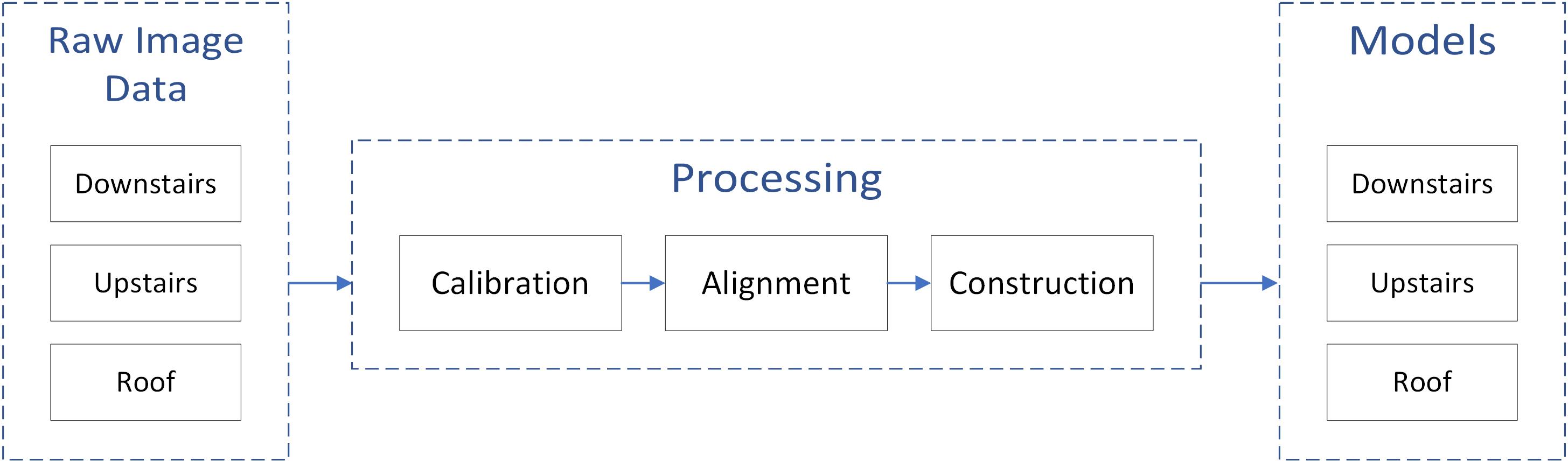 Figure 1. The workflow of photogrammetry processing steps.
2.1. Calibration
The used Nikon camera and selected lens are of high standard, however, due to imperfect camera models, there still exist extortions in the original image, which could be detrimental for photogrammetry purposes. Thus, Intrinsic geometry should be calculated to obtain the correction parameters for lens distortions.
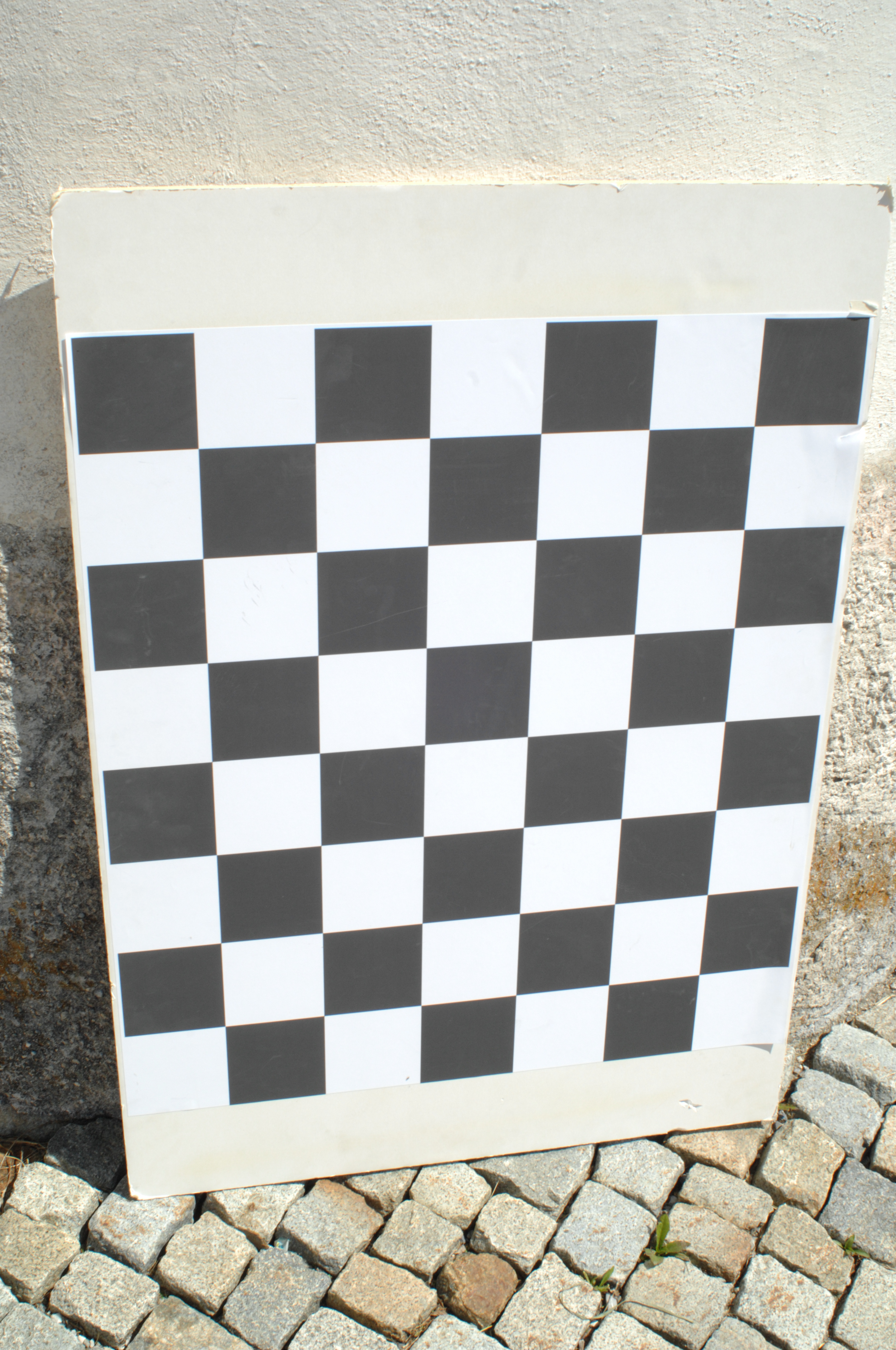 Figure 2. Chess board image taken from outside.
To calculate the camera distortions, we need to provide some sample images of a well-defined pattern (e.g., chess board). We took pictures of the chess board in site with the same parameters used to capture the scene. A sample image is shown on the left. The images of the chessboard were input into the camera calibration function provided by the computer vision toolbox in MATLAB, which could directly detect the edges of the chess board and calculate the intrinsic parameters of the camera. Note that the obtained results are in image space units and need to be converted to world coordinate units. The parameters we use for further Reality Capture processing are radial distortion, tangential distortion, focal length and principal point.
Figure 2. Chess board image taken from outside.
To calculate the camera distortions, we need to provide some sample images of a well-defined pattern (e.g., chess board). We took pictures of the chess board in site with the same parameters used to capture the scene. A sample image is shown on the left. The images of the chessboard were input into the camera calibration function provided by the computer vision toolbox in MATLAB, which could directly detect the edges of the chess board and calculate the intrinsic parameters of the camera. Note that the obtained results are in image space units and need to be converted to world coordinate units. The parameters we use for further Reality Capture processing are radial distortion, tangential distortion, focal length and principal point.
2.2. Alignment of images
The image alignment step is conducted with the inbuilt function in Reality Capture software. As the fundamental principle of photogrammetry is triangulation, common objects in images need to be found to recover the camera position and further calculate the depth information of each image. More specifically, the software first runs a state-of-the-art feature extractor to detect typical feature points in each image. By comparing and matching similar feature points, images are tied together, and the software can obtain the position where each registered images are taken. The result of this step is the already aligned images, with sparse tie point cloud revealing the quality of the matching.
2.3. Constructing 3D model
With the sparse tie-point cloud result we can further construct the model using the reconstruction function in Reality Capture. A depth map is computed for each registered image, which is then combined with other depth maps to establish a dense point cloud. As the depth map computation is conducted on the GPU, to account for the limited processing time, we downsampled each image by a factor of three. Colours and textures from the original images are added to the model. The resulting point clouds and meshes are exported to be ready for comparison with laser scanner models and visualization purposes.
3. Discussion
In the following paragraph the main difficulties encountered are listed.
These problems came from both the acquisition and processing parts.
From the acquisition step:
- The ground floor was very dark, it was necessary to create an artificial illumination coming from flashlights and spotlights, which had to continuously re-arranged to have enough light for every region of interest and also without shadows.
- Monument with many archaeological details. Need special attention when acquiring images.
- High object occlusions, need to acquire a lot of images from different angles.
- Difficulties in adjusting the camera’s parameters to create sharp and clean images.
- Difficulties on sticking the target points, which are needed to geo-referenced the model. Especially in the inside, we were not allowed to place target points due to the fragile frescoes.
From the processing step:
- Since the high number of pictures, the processing software needed a lot of time to align the images, create the tie points and then the final model. Taking into account that different parameters had to be tested the overall process was highly time-consuming.
Overall, the photogrammetric method produced visually satisfactory results, but at the same time, they are not totally complete. Given the difficulties facing during the process, we would argue that this model is not quite suitable for such tasks. Nevertheless, the roof of the chapel was only captured by the camera mounted on the drone, while the laser scanners and the GeoSLAM failed to cover this area. Therefore, the final 3D model is a combination of data captured from photogrammetry and laser scanning.